Final Project
Two nails with a whole lot of potential!
(See tab 12: "Last Days Before Project Is Due!!" for some things that happened in the last few days.) Trouble.
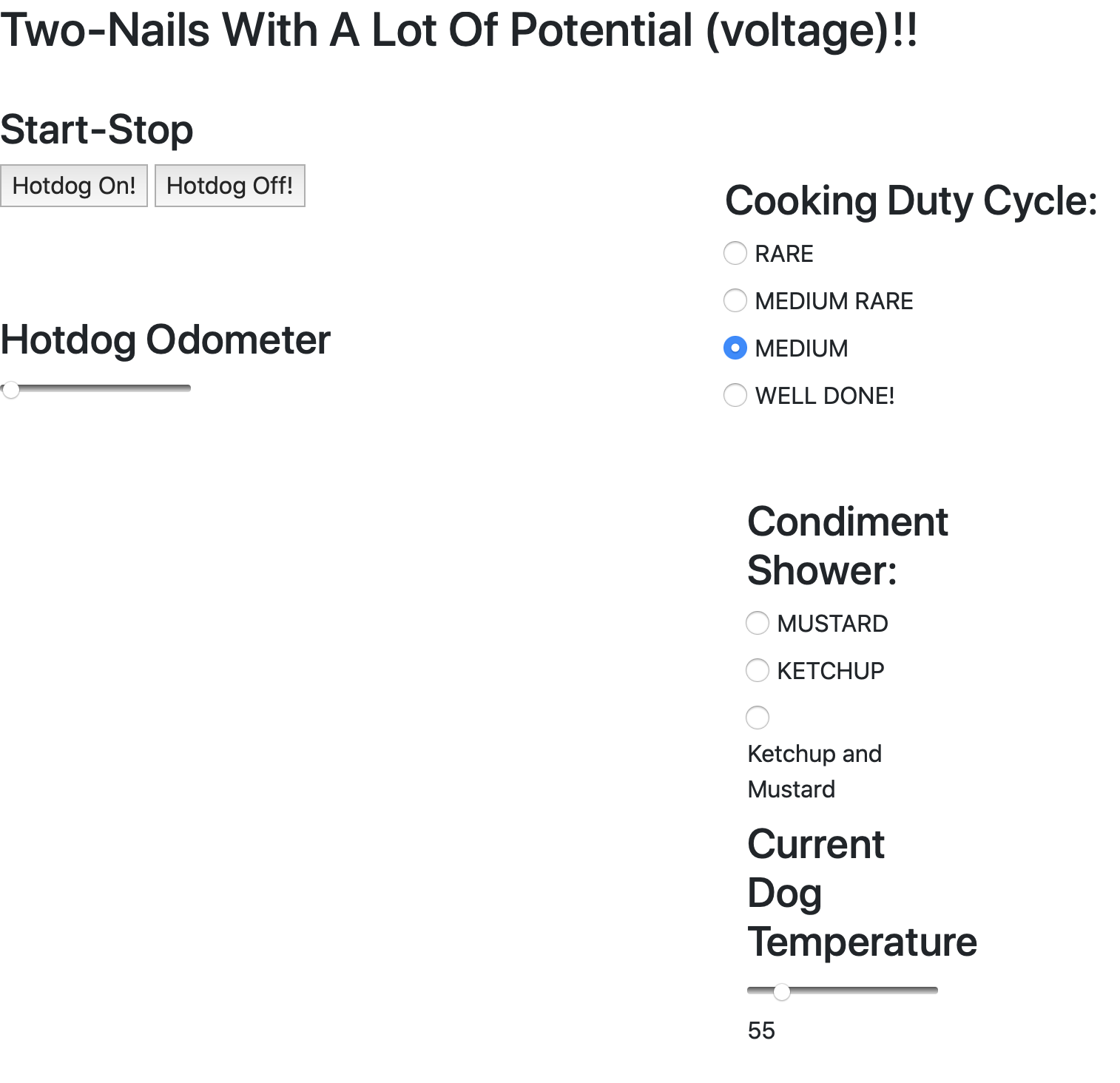
For my final project this summer in Digital Fabrication I have choosen to re-engineer the 1950's "two-nails on a cord" hotdog cooker. I wish there was a higher purpose to my selection of this project focus, but there really is not; the hotdog cooker does not need or want to be re-engineered. However, the cooker is a good platform to incorporate many of the concepts learned in Digital Fabrication this summer. Overall, I spent too much time building my project, and not enough time on documentation. I really ran out of time in the last few days. I wish I had more time to work on the web app so that it could control more of the hotdog cooker. All it can do is turn the cooker "on", and it displays the current hotdog temperature. I had intended to be able to select the desired condiments, cooking cycle, and display the "hotdog odometer!, but out of time.
Pictured below is the original "two-nail" hotdog cooker built during the first week of Digital Fab for experimentation.
This page is a photographic record of the progress of the two-nails cooker project as it has progessed over the last 7 weeks. I have been down many rabbit
holes along the way. This project has come a long way, yet still has a ways to go.
YouTube video of Hotdog Machine:
Return to my home page.
Here is a link to my web app that controls the ESP32 Huzzah board: Hotdog Mission Control.
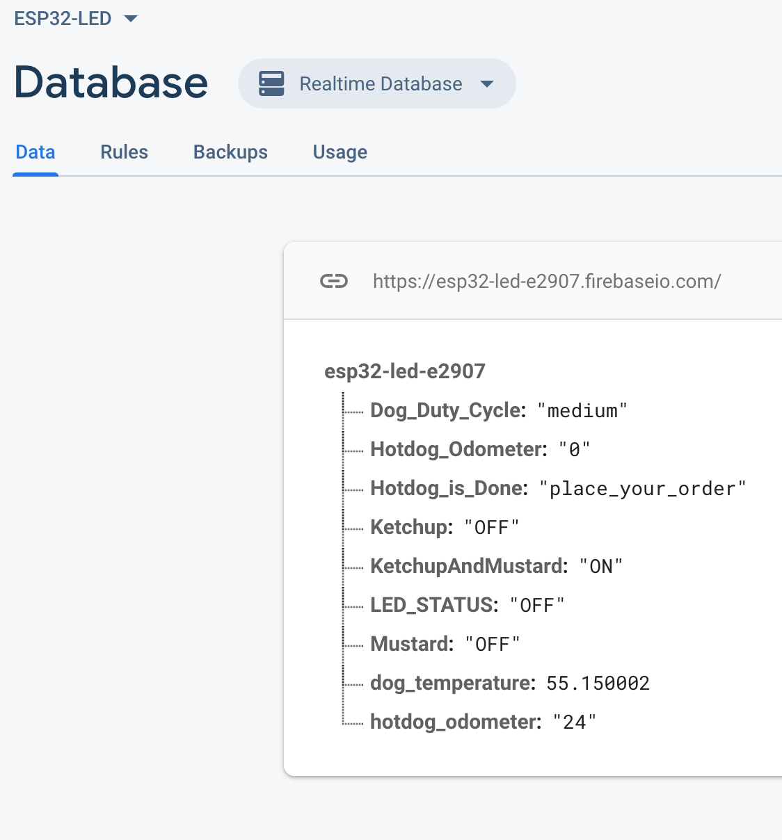
Above is the Firebase database for the hotdog cooker, and the web app is pictured below: (The "hotdog odometer" is not fully functional yet.)
Here is the original sketch of my proposed "website dog app" drawn in the first week or two of S-12:
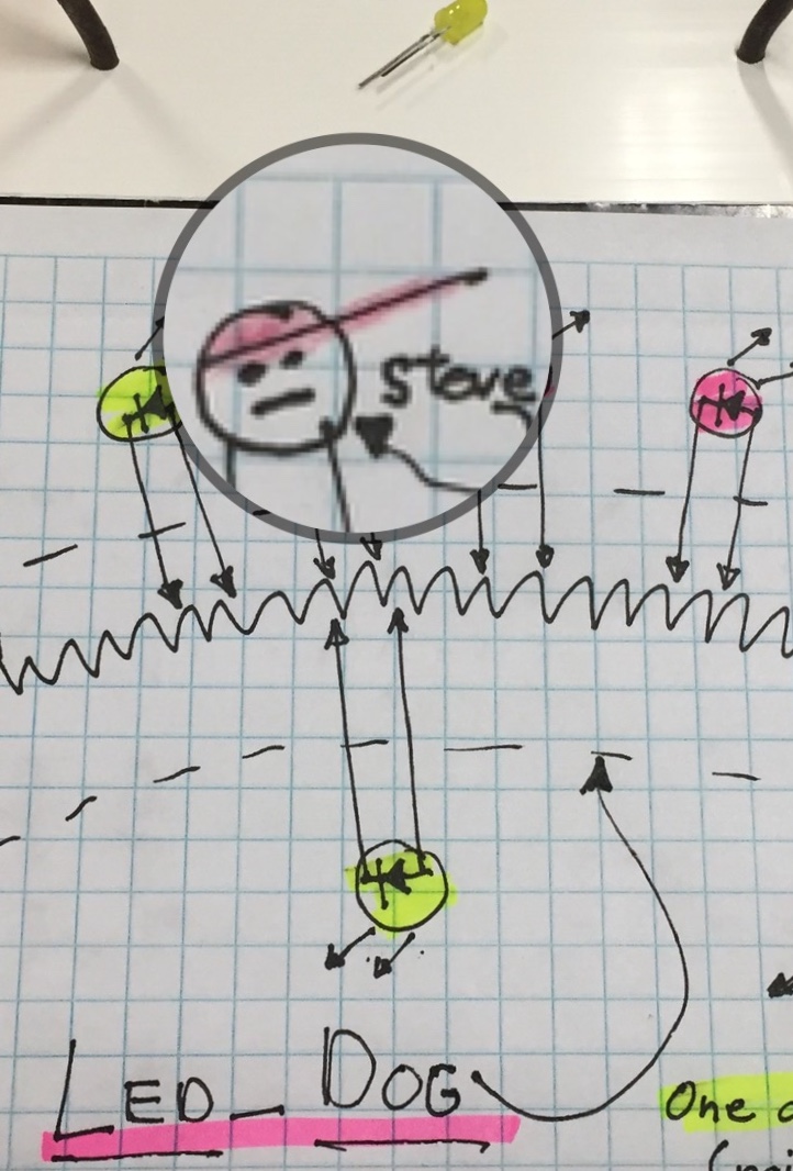
A hotdog is about 1kohms, and there is about 3-5vac across the leds stuck in the dog seen below:
Here is a hotdog with 120 volts applied to the two nails, and leds stuck into it!
This project uses many different voltage sources for the various components:
- 3.3vdc for board inputs and outputs;
- 5.0vdc for USB power to the Huzzah board
- 9.0vdc for power to the Arduino Metro/stepper motors;
- 12.0vdc to open the CO2 solinoid valves (This comes from an old car battery);
- 24.0vdc to power the pre-amp control circuit;
- 120vac to: cook the hotdog, power the second level isolation relays, and all the above power supplies.
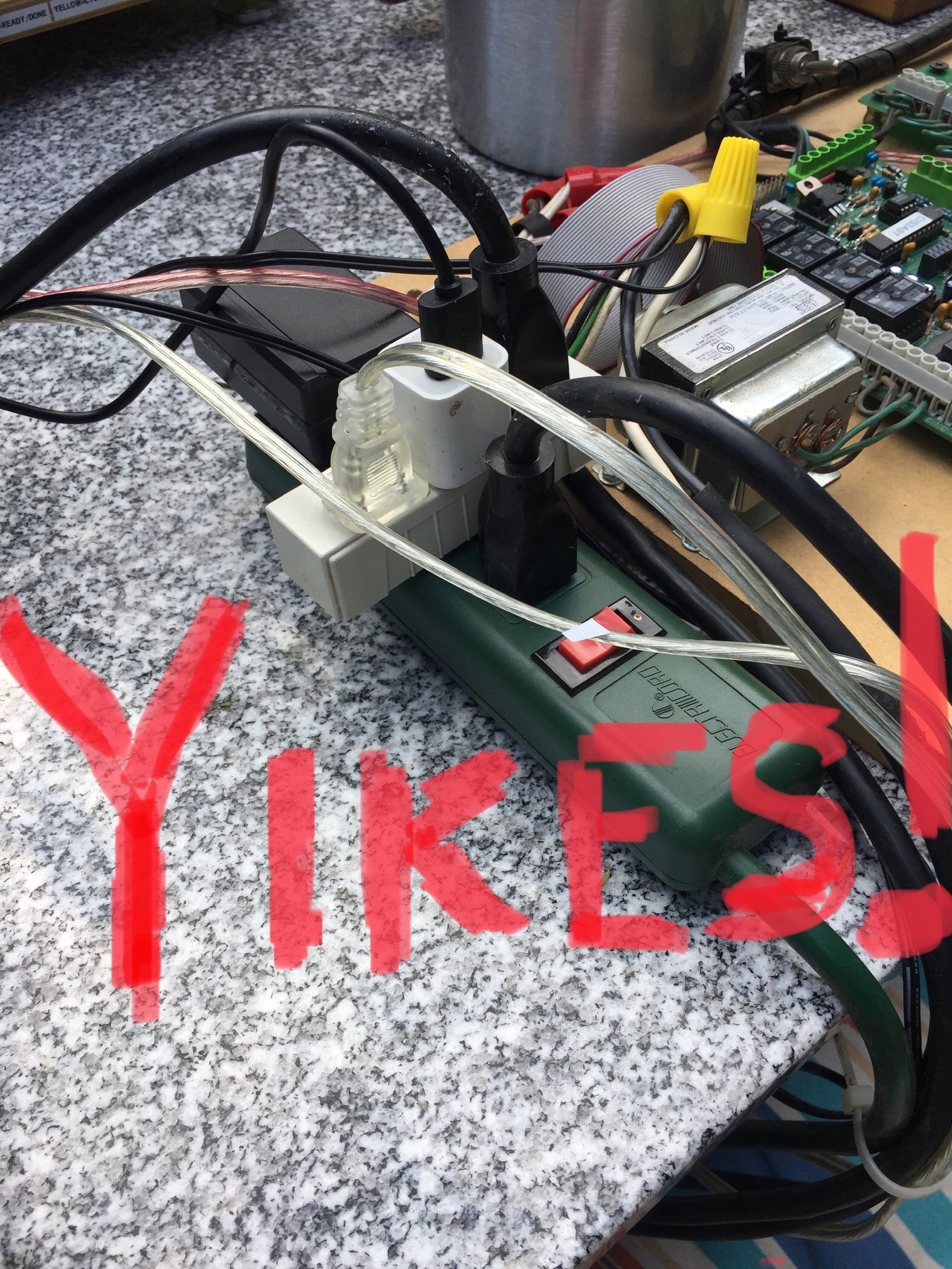
Items Purchased for the Hotdog Machine:
Most of the materials used to construct this project I had around the house/shop. Here are the things I had to purchase:
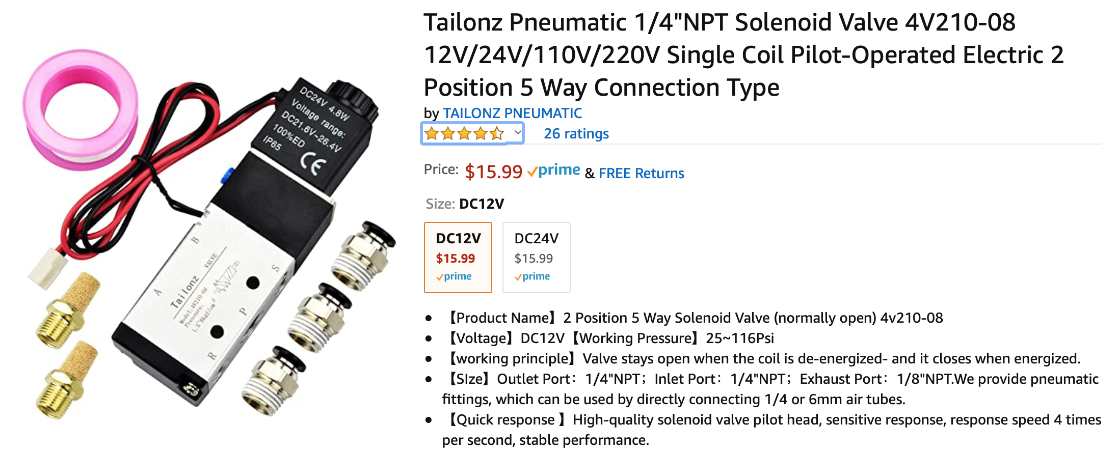


Total cost for the above parts: $107.37!
Link to Kit Parts and Household Materials Used.Shown below are photos of the project's progress:
The cooker chassis is constructed of 3/4" Baltic Birch multi-core plywood, and has a polyurethane finish.
Stepper Motors:
The safety cover is made from half of an acrylic "display case", and is opened and closed by one of two stepper motors that drive a length of 3/8-16 threaded rod. The cover stepper motor runs at 60rpm. I had to add the semi-circular plywood counterweight so that the stepper had enough torque to open and close the cover. The microswitch closes when the safety cover is closed sending 120vac to the solid-state relay.
Below is the 120 volt circuit for the nails, ssr, cover switch etc.
The two-condiment squirter head is moved back and forth over the hotdog by the second stepper motor. This motor runs at 90rpm, and is driving a 1/2-12 threaded rod.
Pictured below are the two H-bridge drivers connected to the stepper motors and the Arduino Metro board for testing of the motor system.
The "two-condiment" squirt head is made from a heavy 1/2-12 nut, super-glued to two 1/2" x 2" washers. I then drilled the washers and squeezed the assembly together with two 6-32 bolts w/nuts for extra strength. This created an attachment point for the two 1/4" nylon tubes that the mustard and ketchup flow through. The tubes ride on the edge of the acrylic cover to maintain the correct orientation as the 1/2" rod is spinning.
A few weeks into the hotdog cooker project I realized my project did not have any type of sensor (as required) so I decided to experiment with a
possible thermocouple to read the hotdog temperature while cooking. (below is a sketch of the possible circuit) The t-couple circuit uses an ice bath
as a reference to create a very small current (approx 1.2 millivolts) at room temperature.
Below is an experiment to see if an industrial thermocouple can be used in place of one of the two nails acting as the "ground electrode" and reading the hotdog temperature to the attached electronic temperature display.
Arduino in TinkerCad:
This sketch shows the wiring for the control switches:
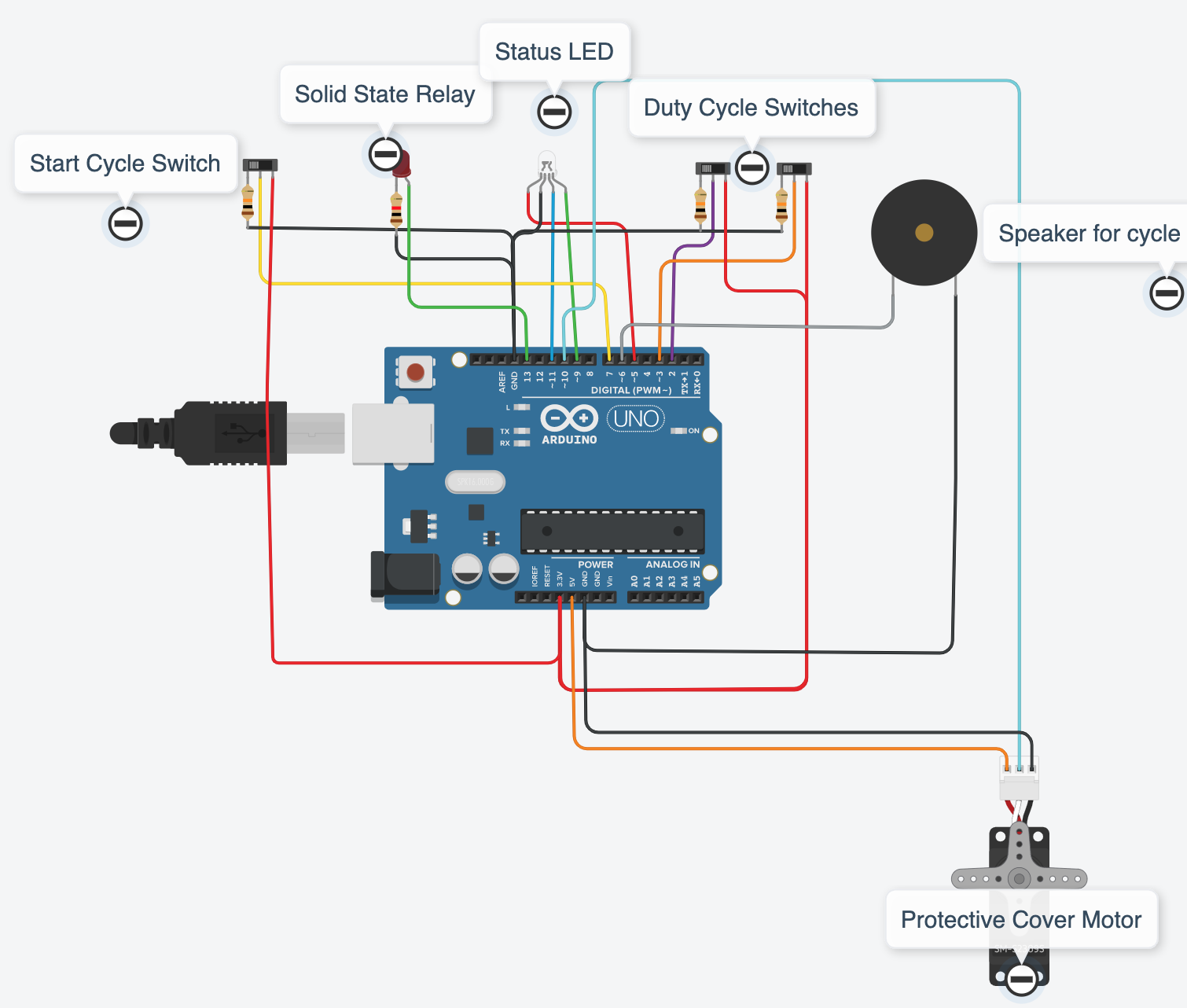
- Start Button/Switch(momentary push button)
- Hotdog Jolt Level Switches
- Speaker/Buzzer
- "Status" RGB LED
- (Servo motor is replaced by a stepper motor in final rev.)
(duty cycle)
This TinkerCad is from pretty early in the hotdog machine process. A few minor things are different in the final version: the RGB led is on pins( 5,SCL,SDA).
Seven Weeks Well Spent!
Thank You!!
Link to Project Sources.
Here are photos of the hotdog cooker on "video day" in my backyard:
Here is the front control panel for the hotdog system. The "status" led is: green when the system is ready or a cycle is complete; yellow when a cooking cycle is active; and red when 120 volts are at the hotdog/nails. "hotdog jolt" percentage is set with two slide switches seen inline with the blue and green leds. Four possible cooking intensities are programmed into the system: 50%, 67%, 75%, and 90%. Condiments are selected by the switch behind the yellow/red leds. The switch behind the red led does not have a function at this time. I had planned to adjust the code to have one switch for mustard and one for ketchup, but did not get to make that modification. With the current Metro and Huzzah codes the condiment options are: mustard and ketchup or just mustard(as shown on the label). The "SSR ON" led is lit when 120vac is being sent to the nails. "CYCLE ACTIVATED" led lights when the "START!" button is pressed or the web app calls for a cycle start. The "START!" button is all the way to the left. The buzzer plays a tone on completion of a hotdog cycle.
The photo below is of the rear of the hotdog project. Behind the breadboard from left to right the following are visible:
- Arduino Metro board;
- "Dog temperature" display(reads a second thermocouple inside the 120vac ground electrode;
- Pre-amp to amplify the very small millivolt output from the thermocouple and send that amplified signal to pin A2 of the Metro board;
- Thermocouple connections. This tc actually has two tc's in the probe. one connected to the water bath/pre-amp and the other to the display;
- Condiment relays which take 3.3vdc inputs from the Metro board to switch 12vdc to the ketchup and mustard solinoid valves.
Below the breadboard at the back of the hotdog machine is pictured. There are no "system input controls" on the back side of the machine. All the control switches are on the breadboard at the front of the machine. The rear board just has some indicator leds, the two stepper motor H-bridges and is a junction point for various connections.
Pictured below are the ketchup and mustard dispensers. They are actually "glue dispensers" purchased from Amazon. Above the dispensers are the two pilot solinoid valves that pass compressed CO2 to the dispensers when energized with 12vdc. You can see some spring clips on the condiment and CO2 tubes as an attempt to restrict the flow of ketchup and mustard. This did not help. I really need regulators on the discharge side of the valves. That way I could maintain the required 25 psi on the inlet side, and control the condiment flow with the regulators on the output side.
The ice bath reference is pictured below with a home-made thermocouple immersed in the 32F water. (sorry of the spelling error on the solo cup!!) This Because this reference thermocouple is at a different temperature than the hotdog thermocouple a very small current/voltage is generated in the circuit, and sent to the pre-amp.
Below the two electrodes of the hotdog cooker are seen. The pointed actual nail on the right is the 120 volt ac electrode. The curved blunt tipped ground electrode, on the left, is actually an industrial thermocouple. It reads the hotdog temperature.
Definitely a two or three napkin situation!
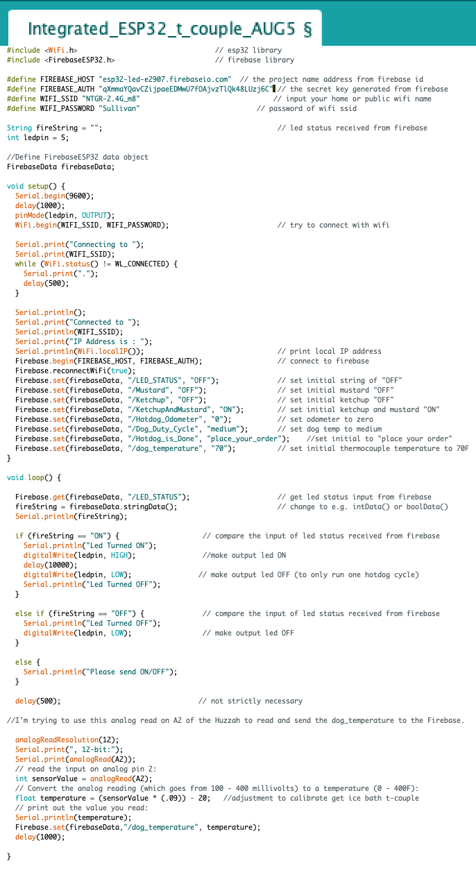
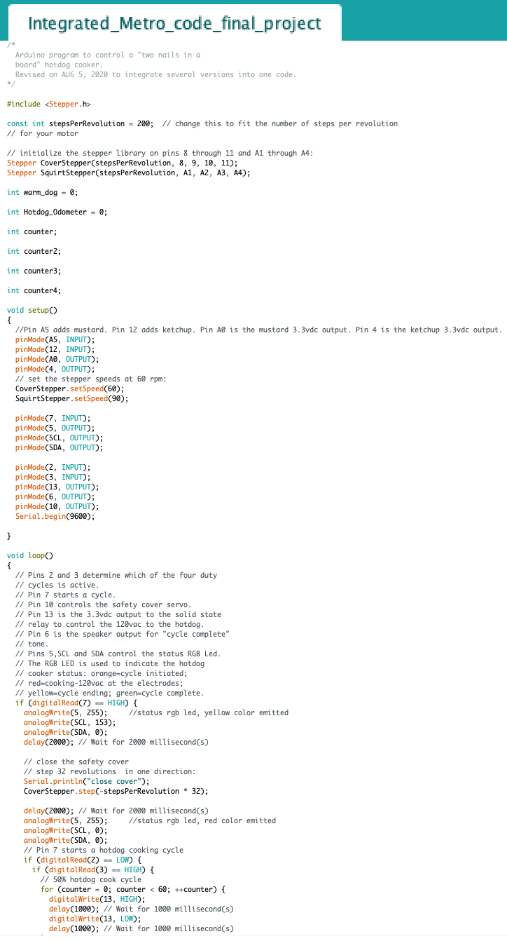
Arduino Code For The Hotdog System:
Arduino code for the ESP32 Huzzah board:
Arduino code for the Metro board:

Addendum to Final Project
Things I have tried since Thursday's final Zoom meeting:
I connected isolation relays to the isolation relays to attempt to eliminate the "mustard stopping the show" glitch. So far so good!, but I have only
run 3 cycles. (I'm running low on ketchup and mustard) I used some Functional Devices, model# RIB21CDC dry contact units that I frequently use at work.
(see several pictures below of the relay on a relay modification)
I also try to correct the "Take Me Out To The Ballgame" should play at the end of a hotdog cycle. I used the block code to write this, and the frequency assignments seem crazy to me-- millions of Hz!. I adjusted them down, but still not working. I will try to find better note to frequency data soon.
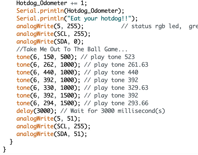
Web App/FireBase:
I would really like to get the "hotdog odometer" function working! I tried a few things, and may have made some progress. However, the odometer is not operational yet.
Stay Tuned!!
Possible Future Hotdog Machine Improvements:
- consolidate the multi-voltage power supplies;
- install bearings on the safety cover pivot points;
- install regulators on the CO2 outputs of the solinoid valves to control condiment flow rate;
- complete the functionality of the web app and FireBase (hotdog odometer etc.);
- get the stepper motors to run faster (possibly a different stepper library??);
- consolidate all elements onto a single chassis;
- use solid-state relays to activate the condiment solinoids(rather than the multi-stage isolation relays);
- some of the indicator LEDs could use resistors to reduce the voltage across them;
- a real front control panel with larger switches(current switches are microscopic--they looked bigger on the internet);
- install a shield so ketchup/mustard doesn't occasionally drip on the Huzzah when the cover is closed;
- many request for relish, chopped onions, and sauerkraut!
- invent "edible LEDs"!!;
- ultimate impovement: robot gripper to load and unload the hotdogs/buns!
I think the ketchup and/or mustard shorted out some of the LEDs. They all worked fine until the "condiment showering" process. Now some of them are not flashing. (Also, I'm not sure if the smoke is coming out of the hotdog's mouth, or..... I don't know how to tell the difference.)